Spring Energized Seals Design Groove Guide
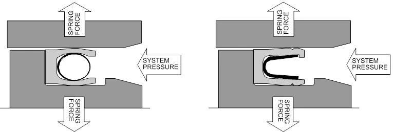
The SES seal is a sealing device consisting of a PTFE or other polymer, energized by a corrosion resistant metal spring. When the seal is seated in the gland, the spring is under compression applying force on the gland sealing surfaces thereby creating a tight barrier to prevent gas or fluids from leaking. The spring also provides resiliency to compensate for seal wear, gland misalignment or eccentricity. While spring force provides adequate force for sealing at low pressure, at high pressure the system pressure augments the spring force to provide an even tighter seal. The SES seals are precision machined from PTFE, filled PTFE and other high performance polymers.
FEATURES AND BENEFITS
Virtually unlimited chemical compatibility (except molten alkali metals, fluorine gas at high temperatures and Chlorine Trifluoride CIF3)
- Low cost alternative to expensive perfluoroelastomers
- Low Friction :
- Smooth and consistent breakout and running friction
- Low power absorption and torque requirements
- Friction can be adjusted and controlled during design
- Can run dry or lubricated
- Wide Temperature And Pressure Range:
- -423 to 600°F,from cryogenic service to hot air or super heated steam
- Vacuum to 60,000 psi, vacuum chambers to high pressure water jet cutters
APPLICATIONS
|
|
SUGGESTED GLAND CONFIGURATIONS FOR ROD SEALS
Since It is not recommended to stretch the Spring Energized PTFE seals,
attached are special design seal grooves that will make it easier to install the seals without stretching them.
Glands are listed in preferential order.
Two Piece Groove.
The two piece groove offers the easiest seal installation, while minimizing the possibility of seal damage during installation.
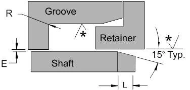
Snap Ring Groove
This type of groove also offers easy seal installation,while allowing flexibility of seal retention methods.
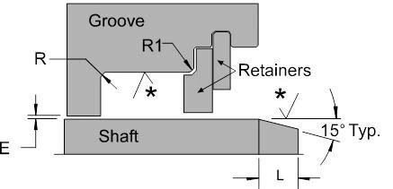
Stepped or Reduced Groove
This type of groove is recommended where there is not enough space to accommodate a two piece groove, or where there was an existing o-ring groove that can be modified.
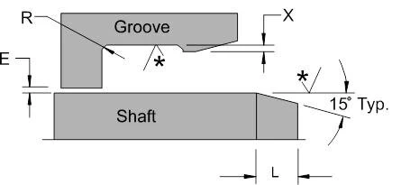
Flanged Groove
This type of groove is recommended mainly for rotary applications, where it is desirable to prevent the seal from rotating in the groove.
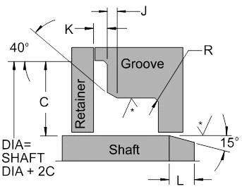
SUGGESTED GLAND CONFIGURATIONS FOR PISTON SEALS
Since It is not recommended to stretch the Spring Energized PTFE seals, attached are special design seal grooves that will make it easier to install the seals without stretching them. Glands are listed in preferential order.
Two Piece Groove
The two piece groove offers the easiest seal installation, while minimizing the possibility of seal damage during installation.
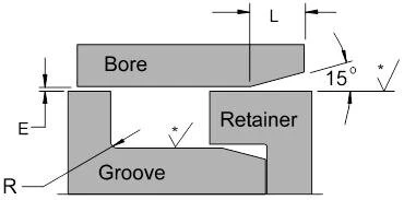
Snap Ring Groove
This type of groove also offers easy seal installation, while allowing flexibility of seal retention methods.
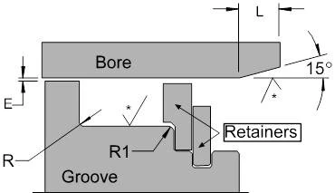
Stepped or Reduced Groove
This type of groove is recommended where there is not enough space to accommodate a two piece groove, or where there was an existing o-ring groove that can be modified.
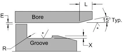
| DASH SIZE | NOMINAL CROSS-SECTION | L MIN. | X +/- .002 | E MAX. | R MAX. | R1 MIN. | K +/- .002 | J +/- .003 | C +/- .004 |
|---|---|---|---|---|---|---|---|---|---|
| -006 thru -046 | 1/16" | 0.075 | 0.010 | 0.003 | 0.015 | 0.030 | 0.012 | 0.012 | 0.158 |
| -106 thru -161 | 3/32" | 0.100 | 0.012 | 0.003 | 0.015 | 0.030 | 0.018 | 0.016 | 0.188 |
| -202 thru -270 | 1/8" | 0.120 | 0.018 | 0.003 | 0.015 | 0.030 | 0.025 | 0.018 | 0.222 |
| -318 thru -377 | 3/16" | 0.150 | 0.022 | 0.004 | 0.020 | 0.060 | 0.030 | 0.028 | 0.347 |
| -405 thru -460 | 1/4" | 0.190 | 0.028 | 0.004 | 0.020 | 0.060 | 0.043 | 0.028 | 0.442 |
HARDWARE SURFACE FINISH AND HARDNESS RECOMMENDATIONS
Dynamic surface finish and hardness play a key role in hardware design.
The figures shown in this page are designed to ensure optimum seal performance. Good surface finish will reduce seal friction and increase seal life, while a high surface hardness will increase seal life as well as protect the hardware from being abraded by the seal material or by contaminants in the system.
| MEDIA | Cryogenics Freon Helium Gas Hydrogen Gas | Air, Argon, Fuels Natural Gas Nitrogen Gas | Water, Crude Oil, Hydraulic Oil High Viscosity Fluids |
|---|---|---|---|
| DYNAMIC SURFACE | 4-8 Ra | 6-12 Ra | 8-16 Ra |
| STATIC SURFACE | 4-8 Ra | 12-32 Ra | 16-32 Ra |
RECOMMENDED HARDNESS FOR SEALING SURFACES
| SERVICE | Static | Rotary | Reciprocating |
|---|---|---|---|
| HARDNESS ROCKWELL "C" SCALE | Any Hardness | Rc 55 Min. | Rc 45 Min. |
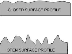
The illustrations show two types of sealing surfaces:
Closed Surface profiles are less abrasive to seals resulting in longer seal life. An open sealing surface tends to abrade and rapidly wear out seals. Roller burnishing process tends to produce better sealing surface areas.
Open Surface profiles are produced by machining processes such as grinding and honing. Some coatings tend to produce rougher sealing surfaces: Hard chrome plating and hard-anodized aluminum tend to produce open surface finishes, therefore is necessary to polish the sealing surface after plating.
RECOMMENDED SEALING SURFACE COATINGS
1.Tungsten Carbide
2.Chromium Oxide
3.Dense Chrome Plating
4.Electroless Nickel plating (polish after plating)
5.Hard Chrome Plating (ground/hone and polish after plating)
6.Hard Anodizing (polish after plating)
SEAL INSTALLATION AND INSTALLATION TOOLS
The proper installation and the use of appropriate installation tools is imperative for the correct functioning of the seals. Most seal failures can be attributed to damaged seals resulting from improper installation.
Although Spring Energized Seals can be slightly stretched or compressed, (see below table), it is strongly recommended to avoid one piece glands (non split). If it is absolutely necessary to use one piece glands, follow the suggestions on gland design and use proper installation tools. (Avoid the use of screw drivers and other metal tools, since the seals can be easily scratched and leakage will result).
To install seals into split or reduced glands, as recommended previous pages, no tooling is necessary, since the seals can be easily installing by using finger pressure.
MAXIMUM % OF SEAL STRETCH OR COMPRESSION RECOMMENDED
| PISTON SEAL (STRETCH) | ROD SEALS (COMPRESS) | ||
|---|---|---|---|
| FINGER SPRING | COIL SPRING | FINGER SPRING | COIL SPRING |
| 8% | 15% | 8% | 12% |
SEAL INSTALLATION AND INSTALLATION TOOLS
Installation of Piston Seal Into a Closed Gland
When installing MSE Seals into blind glands it is important not to overstress the seal material or the spring at localized points. In order to stretch the seal evenly, the use of a ramp and pushing devise are recommended. After stretching, the seal will partially return to its original size. To ensure total recovery, the seal needs to be resized with a tool, which has the same inside diameter as the bore of the hardware.
The installation tools can be made out of Acetal, UHMW (Ultra High Molecular Weight Polyethylene), PFA or PTFE.

Installation of Rod Seals Into Closed Glands
To minimize the possibility of damage to the seal during installation, it is recommended to make the gland width at least 1.5 times the width of the seal plus a 450 angle at the front of the groove. The seal should be installed sideways until one side rest in the groove, then with the help of a pushing tool work the rest of the seal into the groove. With the opposite end of the tool, resize the seal into the groove. The installation procedure can be eased by lubricants and by heating up the seal before installation.

METAL SPRING MATERIALS FOR PTFE SEALS
Spring Materials
| Element | 301 SS | 304 SS | 316 SS | 17-7 PH | EGILOY |
|---|---|---|---|---|---|
| Carbon (C), % | 0.15 -2.0 | 0.08 - 2.0 | 0.08 max | 0.09 max | 0.10 |
| Silicone (Si) | 1.0 max | 1.0 max | 1.0 max | 1 | |
| Phosphorus (P) | 0.045 max | 0.045 max | 0.045 max | 0.04 | |
| Sulphur (S) | 0.03 max | 0.03 max | 0.03 max | 0.03 | |
| Chromium (Cr) | 16-18 | 18-20 | 16-18 | 16-18 | 20 |
| Nickel (Ni) | 6-8 | 8-12 | 10-14 | 6.50-7.75 | 15.00 |
| Manganese (Mn) | 2.0 max | 1 | 2 | ||
| Molybdenum (Mo) | 2-3 | 7 | |||
| Cobalt (Co) | 40 | ||||
| Berylium (Be) | 0.04 | ||||
| Aluminum (Al) | 1.125 | ||||
| Iron (Fe) | Balance | Balance | Balance | Balance | Balance |
Typical Physical Properties for Various Conditions
| Element | 301 SS | 304 SS | 316 SS | 17-7 PH | 17-7 PH | EGILOY | EGILOY | EGILOY |
|---|---|---|---|---|---|---|---|---|
| Condition | FH | 1/2 H | 1/2 H | Condition C | Cond. A +HT RH950 | 45% CR | 40% CR + HT 900°F / 5 hrs | 85% CR |
| Tensile Strength, psi | 185,000 | 150,000 | 176,000 | 220,000 | 220,000 | 220,000 | 245,000 | 330,000 |
| Yield Strength, psi | 140,000 | 110,000 | 147,000 | 190,000 | 190,000 | 185,000 | 230,000 | 305,000 |
| Elongation, % | 8 | 6 | 8 | 5 | 5 | 4 | 2.5 | 2.5 |
| Hardness, Rc | 41 | 32 | 36 | 43 | 43 | 47 | 54 | 50 |
| Density, Lb/in3 | 0.29 | 0.29 | 0.29 | 0.28 | 0.28 | 0.3 | 0.3 | 0.3 |
| Temperature Rating | 500°F | 450°F | 400°F | 600°F | 600°F | 600°F | 600°F | 600°F |
| Corrosion Resistance | Good | Good | Better | Better | Better | Best | Best | Best |
