Your O-Ring Groove Design Checklist
Some seal failures are easy to explain: the wrong material, poor chemical compatibility, or damage during installation. But then there are the frustrating failures. Those are the ones where the o-ring is the right size, the material matches the application, and yet … it leaks. Or it wears out too fast. Or it’s nearly impossible to install correctly.
In many of those cases, the problem isn’t the o-ring. It’s the groove.
Groove geometry is one of the most common (and most overlooked) causes of seal failure. A groove that’s too deep or too wide, cut with the wrong tolerances, or mismatched to the o-ring’s motion or media can undermine even the best material choice.
The best time to address groove design issues is at the very start. To minimize downtime and ensure success, learn what makes o-ring groove designs successful before you begin.
Understand Your Application’s Impact on Your Groove Design
Before designing an o-ring groove, engineers should consider what the seal will actually experience in the field. Factors like pressure, movement, media, and temperature directly influence which groove specs will hold up over time.
One of the most important distinctions is whether the seal is static or dynamic. Static applications involve no movement, so the groove mainly needs to maintain consistent compression. Dynamic seals, on the other hand, introduce motion that increases friction and wear. For those, engineers often rely on externally or internally lubricated o-rings or an applied lubricant like O-Lube to reduce drag and extend life. Without accounting for motion, it’s easy to end up with a groove that performs well in CAD but fails in service.
Environmental stress is another common reason grooves fail. High pressure can push o-rings into extrusion gaps, especially if backup rings weren’t considered. Broad temperature swings can cause thermal expansion, altering compression levels and increasing failure risk. If a fluid causes the o-ring to swell, the groove might overfill and generate excess stress.
Material selection plays a big role in how grooves perform under chemical exposure. Certain compounds absorb media or degrade over time, which can change the seal’s dimensions. Combined with the wrong groove shape or size, this can compromise sealing performance.
Temperature and media also affect long-term stability. The wrong choice can lead to premature hardening, compression set, or shrinkage. All of this reinforces the need to design grooves based on real-world exposure, not just theoretical specs.
Even dynamic load cycles or technician variability during assembly can create tolerance stack-ups that stress the groove geometry. That’s why best practice starts with understanding the entire application environment, then adjusting groove dimensions to suit.
Determine the Core Groove Dimensions
Once the application conditions are clear, you should define the groove geometry. Every groove should be tailored to support proper sealing compression and allow for environmental shifts, material behavior, and installation realities.
The core dimensions to focus on are groove width, depth, squeeze, and either stretch or interference (depending on whether the o-ring seals against an inner or outer diameter). Each one plays a role in how the o-ring behaves once installed.
The groove must be wide enough to accommodate the o-ring’s expansion due to swell or thermal growth, but not so wide that the o-ring rolls or shifts during assembly. Groove depth determines squeeze, which is the amount the o-ring is compressed between the sealing surfaces. If the depth is too shallow, the o-ring can be over-compressed and degrade faster. Too deep, and the o-ring won’t seal effectively.
Squeeze is what creates the sealing force. For most elastomeric o-rings, 20 percent to 30 percent compression is typical, but the right value depends on the application. Dynamic seals often call for less squeeze in order to reduce friction, while static seals may tolerate more.
Stretch applies when the o-ring fits over a shaft or male component. Too much stretch creates internal stress that can cause failure. Interference serves the same function for outer diameter seals, ensuring the o-ring stays in place and maintains compression.
It’s also important to avoid sharp corners that can damage the o-ring during installation. A small radius at the base of the groove helps prevent nicks or cuts that compromise performance.
When these dimensions are tuned together, they create a groove that supports sealing throughout the o-ring’s entire lifecycle, not just at initial install.
Account for Tolerances and Assembly
O-ring groove design isn’t finished when the dimensions are set. Manufacturing tolerances and assembly conditions introduce variation that must be accounted for if the seal is expected to perform consistently.
A groove machined at the high or low end of its tolerance range can significantly affect squeeze. Excess depth reduces compression, while insufficient depth can over-compress the o-ring and thereby increase wear or risk extrusion. Groove width tolerances also influence gland fill and the o-ring’s ability to expand under thermal or chemical conditions.
Small deviations in groove geometry often cause large performance issues in the field. These include premature leaks, inconsistent compression set, and sealing failures under pressure or motion.
Surface finish should also be evaluated. For most elastomeric o-ring applications, a sealing surface roughness of less than 16 microinches Ra is recommended. Rougher surfaces may abrade the o-ring or allow microscopic leakage paths.
Assembly introduces additional variables. Misalignment, over-torquing, and inconsistent handling can all affect how the o-ring seats in the groove. Designs that ignore this reality often see reduced seal life or performance variability across production runs.
A robust groove design tolerates normal variation in manufacturing and use. It ensures the o-ring seals as intended in real-world conditions.
Prepare for Pressure and Extrusion
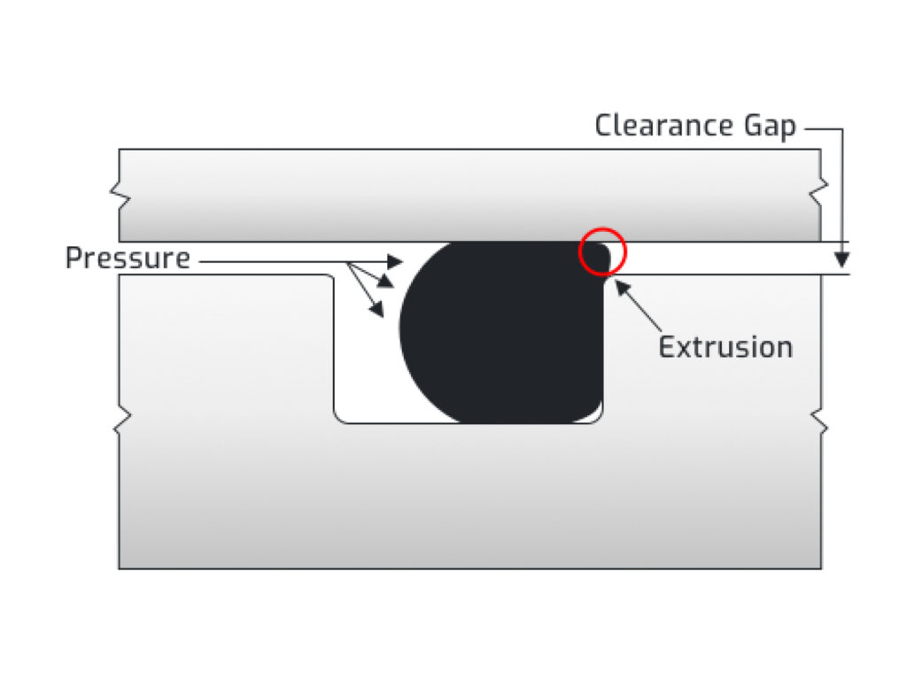
High-pressure applications introduce forces that can push o-rings out of their grooves, especially when there’s an extrusion gap. If the o-ring material is too soft or unsupported, pressure can deform the seal into this gap, leading to extrusion, damage, and eventual failure.
Extrusion risk increases with pressure, temperature, and the gap size between metal components. At pressures above 1,500 psi, even standard elastomers begin to require support. The solution is often backup o-rings, as they reinforce the o-ring and block the extrusion gap without compromising compression.
The groove must be designed to accommodate both the o-ring and the backup ring. This includes verifying that the gland width is sufficient and that the backup material is compatible with both the media and the temperature range. PTFE is commonly used due to its high resistance to extrusion and broad chemical compatibility.
In some cases, backup rings are added to preexisting grooves as a corrective measure when extrusion or blowout occurs. However, the most reliable approach is to design for support from the start, especially in dynamic or pulsating-pressure environments.
Proper evaluation of extrusion risk early in the design phase helps prevent field failures and extends seal life significantly.
Consider Serviceability and Testing
Designing a groove for sealing performance is only part of the equation. The groove also needs to support maintenance, inspection, and replacement throughout the equipment’s lifecycle.
A well-designed groove allows the o-ring to be installed and removed without damage. This means avoiding sharp edges that can tear the seal during assembly and ensuring enough clearance for technicians to access the o-ring when needed. Inaccessible grooves or overly tight fits often result in damaged seals during service or increased labor costs during repairs.
Testing is another essential step. Validation under actual operating conditions, including pressure, temperature, motion, and chemical exposure, gives engineers confidence that the groove will hold up in the field. Testing for compression set, thermal cycling, and real-time aging helps predict long-term behavior and uncover problems that don’t appear during initial assembly.
Even when the groove meets all design criteria, failure to verify performance through testing can lead to costly issues post-deployment. Groove design should always be paired with a testing plan that reflects the realities of how the system will be used.
The Secret to O-Ring Groove Design
O-ring groove design doesn’t get enough attention until the seal fails. By then, it’s often too late to fix it without redesigning hardware, retooling parts, or scrambling to source something nonstandard.
Solving groove-related issues before they happen is the best approach. That means starting with a clear understanding of the application, designing for variation and field conditions, and making groove choices that support long-term performance, not just initial fit.
One of the most effective things you can do early in the process is to design your groove around a standard-size o-ring. Standard sizes are easier to source, available in more materials, and typically more cost-effective. If your hardware can’t support a standard size, then the groove will need to be customized, but the time to address that is now, not later when options are limited.
Ready to pressure-check your groove? Use the checklist below to review key design factors before you commit.
(You can also dive deep into our directory of o-ring groove design guides.)

Groove Design Checklist
Understand Your Application
Set Core Groove Dimensions
Account for Tolerances and Assembly
Design for Pressure and Extrusion
Consider Serviceability and Testing
Smart Sourcing